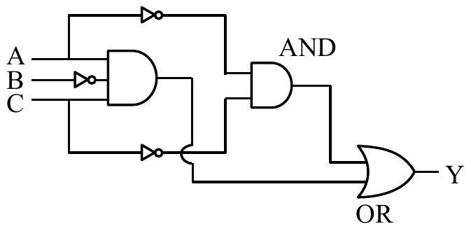
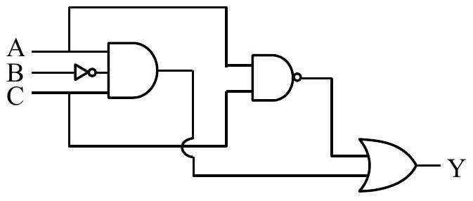
The Boolean expression Y=ABC+AC can be realised with which of the following gate configurations. A. One 3-input AND gate, 3 NOT gates and one 2input OR gate, One 2-input AND gate, B. One 3-input AND gate, 1 NOT gate, One 2input NOR gate and one 2-input OR gate C. 3-input OR gate, 3 NOT gates and one 2-input AND gate Choose the correct answer from the options given below
(A)B, C Only
(B)A,B Only✓ Correct
(C)A, B, C Only
(D)A, C Only
Answer: (B)
Solution
The expression Y=ABˉC+AˉCˉ is a sum of two product terms. The first term ABˉC requires B inverted and then a three-input AND of A,Bˉ,C. The second term AˉCˉ can be built either by inverting A and C and taking a two-input AND, or by recognising that AˉCˉ=A+C, which a single two-input NOR gate gives directly. The two terms are then combined in a two-input OR gate. The arrangement using a three-input AND, three NOT gates, a two-input AND and an OR gate reproduces Y, and so does the one using a three-input AND, one NOT gate, a two-input NOR and an OR gate; an arrangement built around a three-input OR gate cannot. Only those first two gate arrangements realise Y.
JEE Main · 2025 · 04 Apr 2025 · Shift 1 · Single correct option