JEE Main · 2024 · 29 Jan 2024 · Shift 2 · Semiconductors

WhatsApp Email
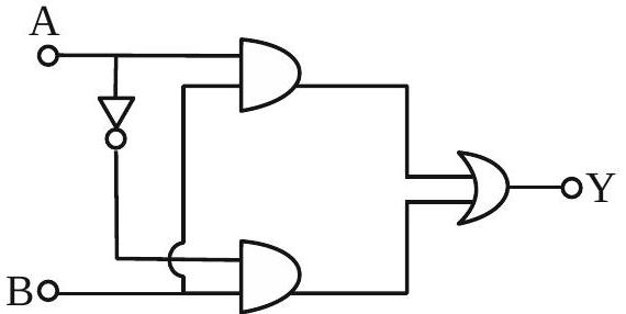
The truth table for this given circuit is :
  1. (A)
    ABY
    001
    011
    101
    110
  2. (B)
    ABY
    000
    011
    100
    111
    ✓ Correct
  3. (C)
    ABY
    000
    010
    100
    111
  4. (D)
    ABY
    001
    010
    101
    110

Answer: (B)

Solution

The circuit combines two AND gates and one OR gate: one AND gate takes inputs A and B, giving ; the other takes (A inverted through a NOT gate) and B, giving . Both outputs feed a final OR gate:


Since for every value of A, this reduces to


So Y is 0 whenever B is 0 and 1 whenever B is 1, independent of A — giving the rows .

JEE Main · 2024 · 29 Jan 2024 · Shift 2 · Single correct option
More JEE Main questions on Semiconductors

  1. Find the correct combination of A, B, C and D inputs which can cause the LED to glow.
    JEE Main 2026View solution →
  2. For the given logic gate circuit, which of the following is the correct truth table?
    JEE Main 2026View solution →
  3. A voltage regulating circuit consisting of Zener diode, having break-down voltage of 10 V and maximum power dissipation of 0.4 W, is operated at 15 V. The approximate value of protective resistance in this circuit is ______ .
    JEE Main 2026View solution →
  4. Identify the correct truth table of the given logical circuit.
    JEE Main 2026View solution →
  5. Two p-n junction diodes and are connected as shown in figure. A and B are input signals and C is the output. The given circuit will function as a ______.
    JEE Main 2026View solution →
  6. The given circuit works as :
    JEE Main 2026View solution →