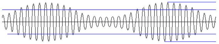
(A)In amplitude modulation the frequency of the high frequency carrier wave is made to vary in proportion to the amplitude of the audio signal.
(B)In frequency modulation the amplitude of the high frequency carrier wave is made to vary in proportion to the amplitude of the audio signal.
(C)In frequency modulation the amplitude of the high frequency carrier wave is made to vary in proportion to the frequency of the audio signal.
(D)In amplitude modulation the amplitude of the high frequency carrier wave is made to vary in proportion to the amplitude of the audio signal.✓ Correct
Answer: (D)
Solution
Modulation is about which property of the carrier is made to follow the message. In amplitude modulation the carrier keeps a fixed frequency and it is the amplitude of the high-frequency carrier that is varied in step with the instantaneous amplitude of the audio signal. In frequency modulation it is the other way round, the amplitude staying constant while the carrier frequency swings with the message. The correct description is that, in amplitude modulation, the amplitude of the carrier is made to vary in proportion to the amplitude of the audio signal.
JEE Main · 2016 · 03 Apr 2016 · Offline · Single correct option