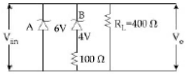
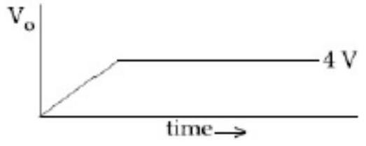
Two Zener diodes (A and B) having breakdown voltages of 6 V and 4 V respe4ctively, are connected as shown in the circuit below. The output voltage V0 variation wlith input voltage linearly increasing with time, is given by: ( Vinput =0 V at t=0 )
(figures are qualitative)
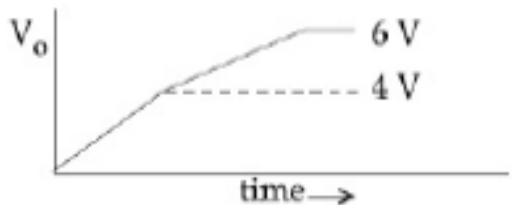
(A)(see structure)✓ Correct
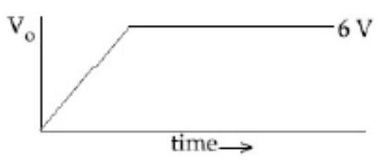
(B)(see structure)
(C)(see structure)
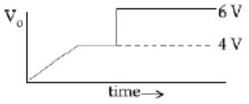
(D)(see structure)
Answer: (A)
Solution
While the input stays below 4 V neither diode has reached breakdown, so the output simply follows the input and climbs linearly. Once the input reaches 4 V the lower-voltage Zener breaks down; between 4 V and 6 V it conducts while the current grows through the series resistance, so the output keeps rising but along a gentler slope rather than holding perfectly flat. When the input passes 6 V the second Zener also conducts and the output settles to a steady clamped level. The correct response is the one that rises straight to 4 V, rises more shallowly from 4 V to 6 V, and saturates beyond 6 V.
JEE Main · 2020 · 05 Sep 2020 · Shift 2 · Single correct option