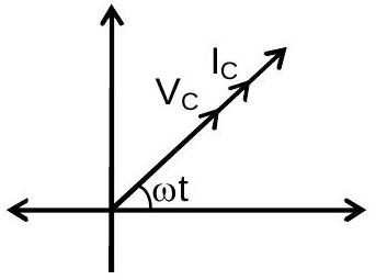
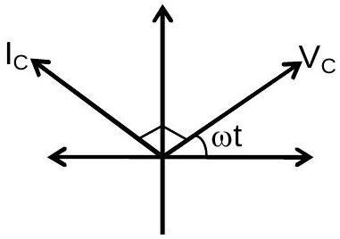
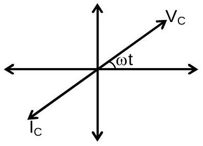
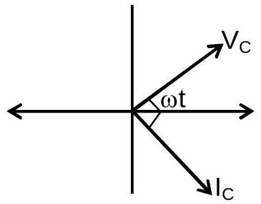
In a circuit consisting of a capacitance and a generator with alternating emf Eg=Eg0sinωt,VC and IC are the voltage and current. Correct phase diagram for such circuit is :
(A)(see structure)
(B)(see structure)✓ Correct
(C)(see structure)
(D)(see structure)
Answer: (B)
Solution
For a pure capacitance the charge follows the voltage, q=CVC with VC=Eg0sinωt, so
IC=dtdq=ωCEg0cosωt=ωCEg0sin(ωt+2π)
The current reaches its peak a quarter cycle earlier than the voltage, so in the rotating phasor picture the voltage phasor sits at angle ωt from the reference axis and the current phasor stands a further 90∘ ahead of it, both turning anticlockwise.
JEE Main · 2021 · 22 Jul 2021 · Shift 2 · Single correct option