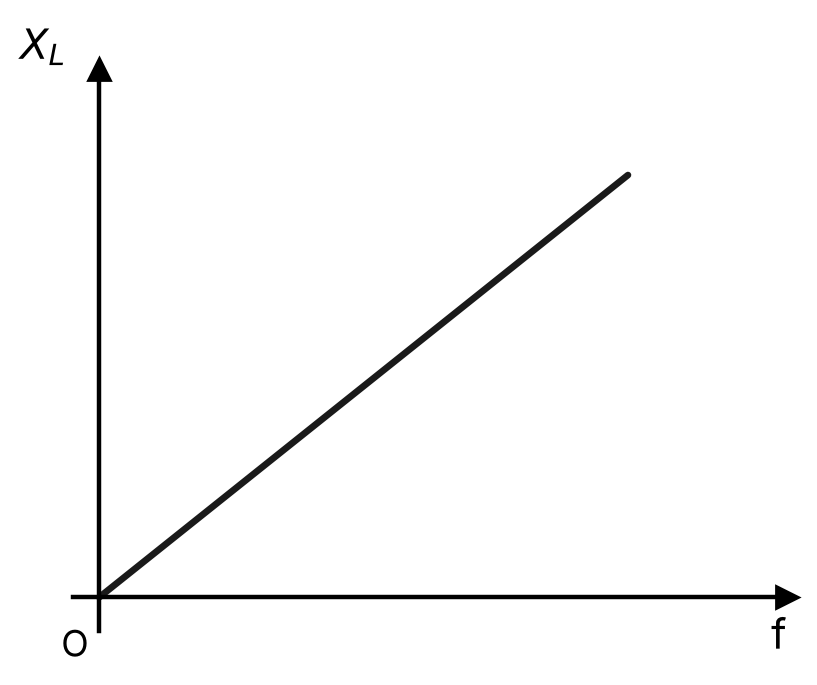
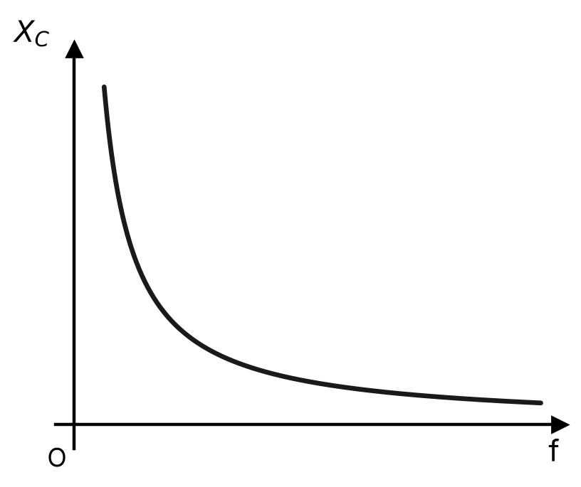
(i) Draw the graphs showing the variation of inductive reactance and capacitive reactance with the frequency of the applied AC source. (ii) Can the voltage drop across the inductor or the capacitor in a series LCR circuit be greater than the applied voltage of the AC source? Justify your answer.
Solution
(i) Inductive reactance XL=2πfL is directly proportional to f, so its graph is a straight line through the origin. Capacitive reactance XC=2πfC1 is inversely proportional to f, so its graph is a rectangular hyperbola falling with increasing f. (ii) Yes. The voltages across L and C are 90∘ out of phase with the resistor voltage and 180∘ out of phase with each other, so they partly cancel. The source voltage is the phasor sum V=VR2+(VL−VC)2, not the arithmetic sum; hence VL or VC individually (especially near resonance) can exceed the applied voltage.