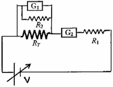
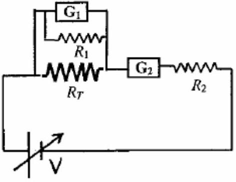
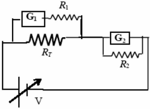
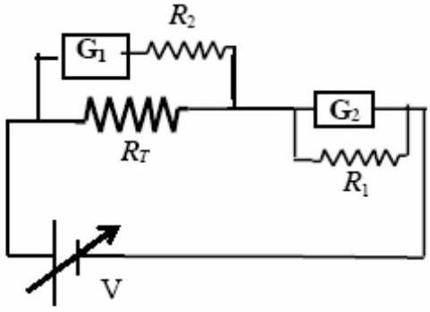
To verify Ohm's law, a student is provided with a test resistor RT, a high resistance R1, a small resistance R2, two identical galvanometers G1 and G2, and a variable voltage source V. The correct circuit to carry out the experiment is
(A)(see structure)
(B)(see structure)
(C)(see structure)✓ Correct
(D)(see structure)
Answer: (C)
Solution
To verify Ohm's law, we need to measure both voltage across and current through the test resistor RT. G1 (with high resistance R1 in series) acts as a voltmeter to measure voltage across RT. G2 (with small shunt resistance R2 in parallel) acts as an ammeter to measure current through RT. The correct configuration has G1+R1 in parallel with RT (voltmeter connection) and G2 with R2 in series with RT (ammeter connection). Circuit (C) shows this arrangement.
JEE Advanced · 2010 · 11 Apr 2010 · Paper 1 · Single correct option