JEE Advanced · 2014 · 25 May 2014 · Paper 1 · Current Electricity

WhatsApp Email
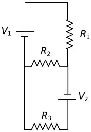
Two ideal batteries of and and three resistances and are connected as shown in the figure. The current in resistance would be zero if
  1. (A) and ✓ Correct
  2. (B) and ✓ Correct
  3. (C) and
  4. (D) and ✓ Correct

Answer: (A), (B), (D)

Solution

Let current through be , through be , and through be .

Kirchhoff's voltage law:
Loop 1:
Loop 2: , which gives

For : From loop 1, . From loop 2, , so .

Dividing: , or .

Checking options:
(A) and : ✓
(B) and : ✓
(C) and : ✗
(D) and : ✓

JEE Advanced · 2014 · 25 May 2014 · Paper 1 · One or more correct options
More JEE Advanced questions on Current Electricity

  1. A metal wire of cross-sectional area and length 100 m is connected across a battery of e.m.f. 2 V and internal resistance . The density, atomic mass and electrical conductivity of the metal are …
    JEE Advanced 2026View solution →
  2. As shown in the figure, the resistance of a galvanometer can be found by the half-deflection method. Here the resistance is adjusted such that when the key is closed the deflection in the galvanometer becomes half of the value as compared to when is op …
    JEE Advanced 2026View solution →
  3. In a circuit shown in the figure, the capacitor is initially uncharged and the key is open. In this condition, a current of 1 A flows through the resistor. The key is closed at time . Which of the following statement(s) is(are) correct?
    [Given: …
    JEE Advanced 2023View solution →
  4. The figure shows a circuit having eight resistances of each, labelled to , and two ideal batteries with voltages and .

    Which of the following statement(s) is(are) correct?
    JEE Advanced 2022View solution →
  5. Two resistances and are connected to a wire of uniform resistivity, as shown in the figure. The radius of the wire varies linearly along its axis from at to at . A galvanometer (G) connected to the center …
    JEE Advanced 2022View solution →
  6. In Circuit-1 and Circuit-2 shown in the figures, and . and are the power dissipations in Circuit-1 and Circuit-2 when the switches and are in open conditions, respectively.
    and …
    JEE Advanced 2022View solution →