JEE Advanced · 2016 · 22 May 2016 · Paper 2 · Current Electricity

WhatsApp Email
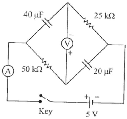
In the circuit shown below, the key is pressed at time . Which of the following statement(s) is(are) true?
  1. (A)The voltmeter displays -5 V as soon as the key is pressed, and displays +5 V after a long time✓ Correct
  2. (B)The voltmeter will display 0 V at time seconds✓ Correct
  3. (C)The current in the ammeter becomes of the initial value after 1 second✓ Correct
  4. (D)The current in the ammeter becomes zero after a long time✓ Correct

Answer: (A), (B), (C), (D)

Solution

At , capacitors are uncharged, so voltage across each is zero. The voltmeter reads the voltage across the 50kΩ resistor minus the voltage across the 40μF capacitor, which is -5V initially. ✓ (A)

At , capacitors are fully charged and no current flows. Voltmeter reads +5V. ✓ (A)

The time constant s. Current decays as , so at s, . ✓ (C)

At , current becomes zero. ✓ (D)

Voltmeter reading: . At , . ✓ (B)

JEE Advanced · 2016 · 22 May 2016 · Paper 2 · One or more correct options
More JEE Advanced questions on Current Electricity

  1. A metal wire of cross-sectional area and length 100 m is connected across a battery of e.m.f. 2 V and internal resistance . The density, atomic mass and electrical conductivity of the metal are …
    JEE Advanced 2026View solution →
  2. As shown in the figure, the resistance of a galvanometer can be found by the half-deflection method. Here the resistance is adjusted such that when the key is closed the deflection in the galvanometer becomes half of the value as compared to when is op …
    JEE Advanced 2026View solution →
  3. In a circuit shown in the figure, the capacitor is initially uncharged and the key is open. In this condition, a current of 1 A flows through the resistor. The key is closed at time . Which of the following statement(s) is(are) correct?
    [Given: …
    JEE Advanced 2023View solution →
  4. The figure shows a circuit having eight resistances of each, labelled to , and two ideal batteries with voltages and .

    Which of the following statement(s) is(are) correct?
    JEE Advanced 2022View solution →
  5. Two resistances and are connected to a wire of uniform resistivity, as shown in the figure. The radius of the wire varies linearly along its axis from at to at . A galvanometer (G) connected to the center …
    JEE Advanced 2022View solution →
  6. In Circuit-1 and Circuit-2 shown in the figures, and . and are the power dissipations in Circuit-1 and Circuit-2 when the switches and are in open conditions, respectively.
    and …
    JEE Advanced 2022View solution →